Content
A cable tray roll forming machine has to do more than bend strip into a U or a hat. It must hold the tray width, keep side walls square, place holes where the installer needs them, and repeat the same result after a size change. That is why two specifications deserve attention early in the buying process: auto-width adjustment and inline punching. Together they decide how quickly a line moves from one tray family to another and whether perforated trays are produced in one continuous pass rather than through a slower secondary operation.
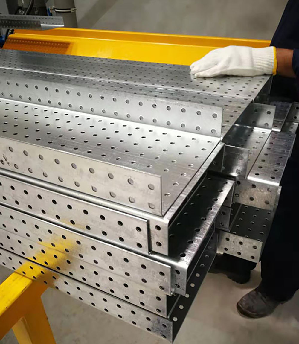
Solid tray is mainly a forming and cutting task. The strip runs through a series of driven stands, the side walls are gradually raised, and the finished profile is cut to length. Perforated tray adds a hole-making step. Because base patterns and many side holes are easier to punch while the strip is still flat, pre-punching is common. Slot patterns such as 6 x 30 mm or 8 x 35 mm may be used, but the exact layout should follow the tray standard and the installer’s fixing method.
If holes are punched after forming, the tooling must reach into the formed section. This can work for simple patterns, but it is less forgiving on deep side walls and high hole density. For buyers comparing equipment, the first filter is not the number of stands. It is whether the line can handle the required hole layout, hole-to-edge distance and scrap removal without marking the strip. A dedicated cable tray roll forming machine platform should be specified around those constraints, not around one tray size.
 Automated Cable Tray Roll Forming MachineView this automated line when hole layout, edge distance and scrap removal drive specification; it integrates punching, forming and cutting for metal cable trays.View Product →
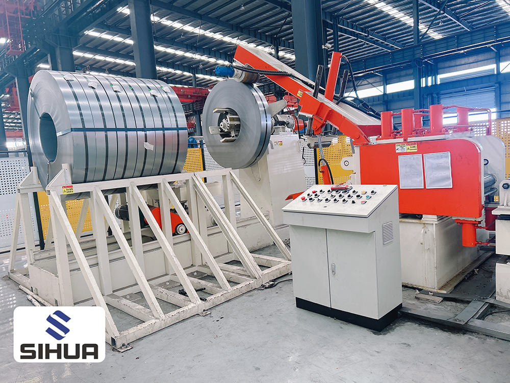
A typical cable tray line follows a clear sequence. Each step affects the next, so the specification should cover the whole cell rather than the forming mill alone.
Inline punching is not one design. The right route depends on hole position, pattern density, strip thickness and changeover expectations.
Holes are punched before the strip enters the forming stands. This is usually the most stable route for base patterns and side holes because the tooling works on a flat surface. It also makes slug removal easier. The trade-off is that the strip must be tracked accurately so the hole pattern stays centered after forming.
Punching after forming can be useful for holes that are difficult to place on a flat strip or for simple patterns added late in the process. It requires special tooling access and can slow the line if the punch station becomes the bottleneck.
When only a few holes are needed, punching close to the cut-off can simplify the line. However, complex patterns usually favor a separate punching station with dedicated tooling and scrap control. For high-density work, a multi-axis servo punching unit can move the strip or tooling in several directions and store pattern recipes. The same servo discipline is used in other automated lines, such as the 8-axis servo punching machine for solar PV bracket roll forming. For cable tray buyers, the lesson is to count the controlled axes and pattern changes, not just the press tonnage.
 1.8-Axis Servo Punching Solar PV Bracket Roll Forming MachineReview this integrated line for flexible punching positions and automatic width and height changes when solar bracket profiles require synchronized punching and forming.View Product →
Auto-width adjustment is often described as a way to change tray width without changing rolls. In practice, the machine may move edge guides, side rolls or entire forming heads within a designed width envelope. It can reduce changeover from hours to minutes when the next job stays inside the same profile family. It does not automatically change profile height, strip thickness, hole pattern or cut-off die.
Use the table below to turn a broad request into a line specification. It helps separate what the machine must do every day from what it may only need occasionally.
| Decision area | What to define | Why it matters |
|---|---|---|
| Tray type | Perforated, solid, ladder, trough or cover | Determines punching, forming and cut-off tooling |
| Width envelope | Smallest and largest tray width | Sets the auto-width range and roll shaft length |
| Strip thickness | Minimum, maximum and typical coil gauge | Affects stand power, roll pressure and springback |
| Hole pattern | Slot size, pitch, edge distance and side-hole position | Defines punching route, tooling and scrap removal |
| Changeover target | Width-only change versus full profile change | Reveals whether auto-width adjustment is enough |
| Output target | Meters per shift by profile and pattern | Prevents line speed from being mistaken for real capacity |
Line speed is a headline number, not a production rate. In perforated tray production, the bottleneck often sits at the punch station, the cut-off or coil changes. A dense hole pattern can slow the line even when the forming mill is capable of higher speed. Output per shift should be calculated from strip speed, hole pattern, cut length, coil weight and changeover allowance.
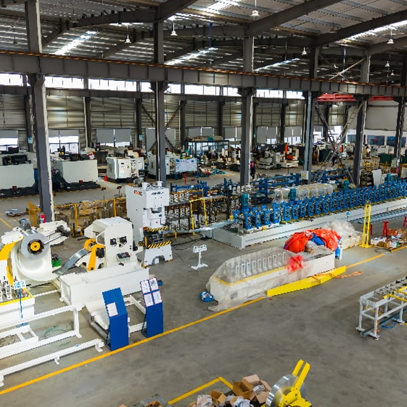
Cut-off design matters as much as forming speed. A look at high-speed shearing technology shows why fly-shear synchronization and blade maintenance affect uptime. Price the whole cell, including decoiler, leveler, punching, forming, cut-off, runout, stacking or packaging, commissioning and training. A slightly slower line with fast width changes can beat a faster line on mixed orders.
Acceptance should be based on parts, not brochures. Run the widest and narrowest tray in the envelope, the thinnest and thickest strip, and at least one perforated pattern. Then check the points that affect daily production:
Ask for the maintenance schedule and spare-parts list before shipment. It is also useful to review installed equipment cases and speak with owners running similar tray profiles.
Yes, if the line is specified for both. Solid trays may bypass the punch station, while perforated trays need the correct punch tooling, slug removal and pattern control. The changeover procedure should be demonstrated before acceptance.
Only within the designed width envelope and profile family. It can move guides and forming positions automatically, but it does not replace every roll set for a new profile height, thickness range or hole pattern.
Not always. Flat-strip pre-punching is usually more stable for dense patterns. Post-forming punching can suit simple holes or special access, but it may limit speed and tooling reach.
Send tray drawings, width and thickness ranges, hole layout, coil data, target output and changeover expectations. That lets the supplier quote the full line and confirm whether auto-width adjustment and inline punching fit the order mix.
An automatic C-U-sigma multi-profile roll forming production line can produce various structural profiles of C, U, and sigma types. It adopts a 3-in-1 feed rack integrating decoiling, leveling, and fe...
See Details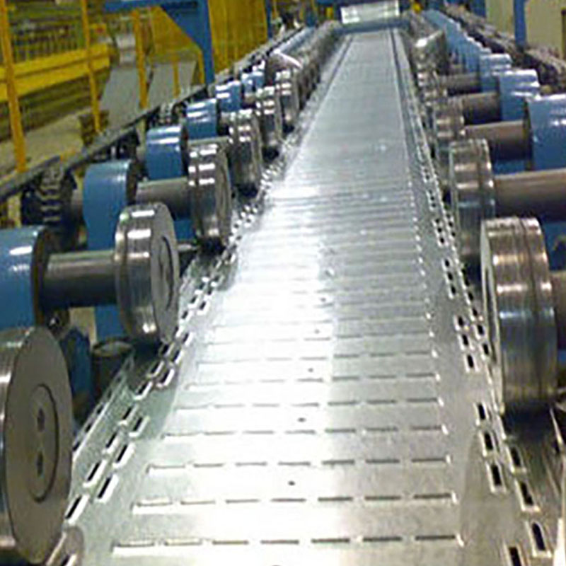
Cable tray roll forming machine with adjustable width Single head belt brake decoiler with leveling machine Custom-made long and wide punch press machine A buffer space is needed b...
See Details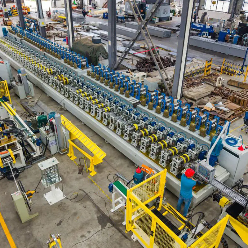
Decoiler System COMBI 3/1 decoiler lever and feeder Capacity: 3-8 tons high feeding accuracy, fully automatic operation, widely used for metal coil stamping Punch Press Unit Punching fo...
See Details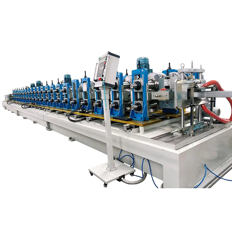
Decoiler System Double-Head Rotary Hydraulic Decoiler Capacity: 3 tons × 2 pieces Maximum material width ≤ 800 mm Hydraulic expansion coil Hydraulic expansion coil o Motor rotary exchange for...
See Details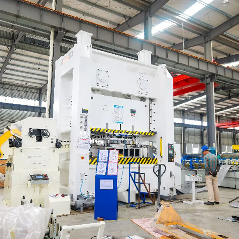
Decoiler System 3-in-1 Decoiler Straightener Feeder Capacity: 5 tons hydraulic coil mandrel expansion, servo feeding & straightening. Punching machine 400 Ton Power Press Capacity: ...
See Details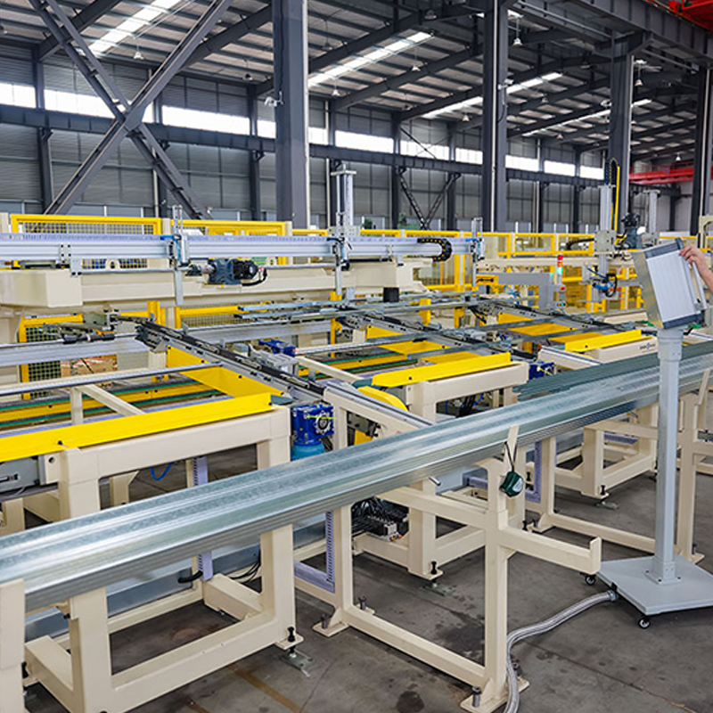
Automatic button flipping machine Flipping speed: 120 meters per minute. Flips the metal profile and snaps it on. Small bundle packing machine Large bundle palletizer Large-bu...
See DetailsDon't hesitate to contact when you need us!
Contact Information
PRODUCTS
Mobile


 English
 Español
 русский