Content
An 8-axis servo punching machine turns holemaking into a synchronized step inside a PV bracket roll forming line. Instead of drilling or punching brackets after cutting, the line can create attachment holes, grounding points, and adjustment slots in one continuous flow. The result is fewer handling steps and more consistent patterns across changing bracket designs. This article explains where the technology fits, how to integrate it, and what to verify before specifying a line.
PV brackets are rarely simple. A single order can include C, Z, Omega, hat, or custom profiles with holes for rail attachment, clamp mounting, grounding, cable routing, and dimensional adjustment. If those holes are made offline, every bracket may be cut, moved, stacked, punched, and returned to the line. That adds labor, floor traffic, and risk of pattern drift or surface damage.
Inline multi-pattern punching removes that loop. The punching unit works from the same strip and the same line control as the roll former, so hole position is tied to feed length rather than to a separate operator setup. The approach is most valuable when a product family shares a profile but changes hole spacing, hole diameter, or cluster arrangement from one project to the next.
An 8-axis servo punching machine uses independent servo motion to control functions such as strip feed, punch actuation, tool positioning, and pattern registration. The exact axis allocation depends on the machine design, but the principle is the same: each motion is programmable and synchronized with the line encoder. This allows holes to be punched at precise intervals, in clusters, or in different patterns without stopping the line for every change.
Multi-pattern capability comes from recipe management and tool arrangement. A recipe can store hole size, pitch, offset, skip patterns, and material thickness. When the operator selects a new bracket, the controller positions the tooling and adjusts the punching sequence. For a closer technical explanation, see this overview of 8-axis servo punching.
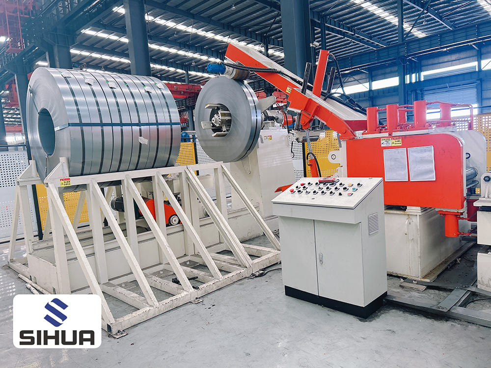 1.8-Axis Servo Punching Solar PV Bracket Roll Forming MachineIntegrated roll forming and precision punching line with recipe-managed multi-pattern capability, ±0.1 mm punching accuracy, and customizable hole positions for solar bracket production.View Product →
The machine can punch flat strip before forming or formed profiles after forming, depending on hole location and distortion risk. Punches on flat strip are usually easier to control; punches on vertical flanges may require after-forming access and additional strip support.
PV bracket hole patterns are defined by the mounting system, not by the punch. Common requirements include round holes for bolts, slotted holes for adjustment, small grounding holes, and repeated clusters for rail or clamp attachment. The integration plan should define hole diameter, position, edge distance, burr direction, flatness, and allowable coating damage.
Material matters. Pre-galvanized or zinc-coated strip can build up on tools, and thin gauges are more sensitive to distortion when holes sit close to an edge. A practical review should separate holes that can be punched inline from holes that should be drilled, laser cut, or punched in a secondary operation because of size, access, or quality risk. This prevents the line from being designed around an unrealistic pattern.
In a typical inline layout, the strip passes from a decoiler through a leveler and servo feed, then into the punching unit, roll former, cutoff, and runout. Some lines place punching after forming so holes can be placed on flanges that are not accessible on flat strip. The best position is determined by hole geometry, tool clearance, strip support, and the risk of profile twist after punching.
Controls are the connective tissue. The punching controller should exchange speed, length, and recipe data with the roll forming controller, and both should share a clear fault and recovery sequence. Slug removal, tool lubrication, scrap collection, and safe access for jam clearing also need to be designed into the line. A punching head that works well on a bench can still fail in production if strip support or scrap handling is weak.
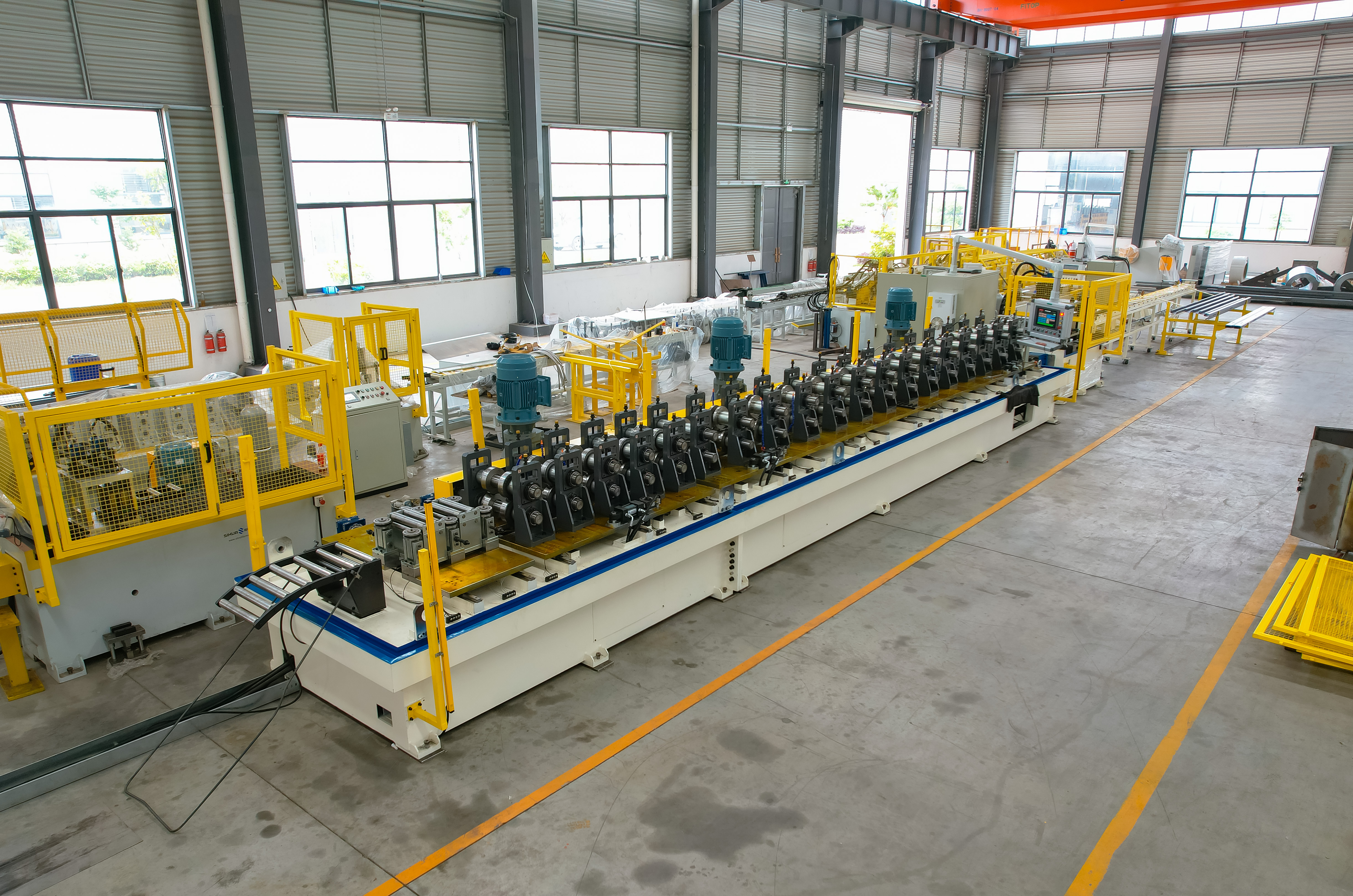 Solar Bracket Auto Change Width Roll Forming MachineAutomatic width and height adjustment line for C-shaped, U-shaped, and Strut Channel profiles, reducing changeover time and supporting diversified photovoltaic bracket orders.View Product →
For bracket families that change width, a solar bracket auto change width roll forming machine can reduce manual adjustment and make recipe changes more repeatable.
Tooling should be specified around the full pattern family, not only the first sample. Quick-change dies, replaceable inserts, and controlled die clearance help manage wear and changeover. For coated material, tool surface finish and clearance affect burr height and coating damage. Sensors for strip presence, tool position, and slug removal reduce the chance of a missed hole or a damaged die.
Quality planning should include first-article approval, hole position checks, burr inspection, and a simple wear record. In production, check the first part after each recipe change and at defined intervals. If the bracket is part of a structural or grounding system, agree on the inspection method before the line is shipped rather than after installation.
Inline punching improves throughput mainly by removing handling and waiting. It also reduces work in process, because brackets do not sit in stacks waiting for a separate punch press. Pattern repeatability improves when the same servo feed and line encoder control both forming and punching. Changeover time depends on tooling design, recipe quality, and how many axes must be repositioned.
The business case should include labor, floor space, scrap, rework, and changeover, not only punch speed. A line that runs slightly slower but changes patterns in minutes can outperform a faster line with long setup delays. For examples of equipment built for continuous production, review these commissioned equipment projects.
Use the checklist below to structure the technical review. The goal is to confirm that the punching unit, roll former, and product design can work as one system.
| Review area | What to confirm |
|---|---|
| Profile family | C, Z, Omega, hat, or custom section |
| Hole pattern | Diameter, pitch, offset, cluster, and slot size |
| Material | Thickness, yield strength, coating, and strip width |
| Line position | Punch before forming or after forming |
| Tooling | Quick change, clearance, slug removal, and wear parts |
| Quality | Position tolerance, burr, flatness, and coating damage |
| Control | Recipe storage, encoder sync, and fault recovery |
It is the ability to punch several hole sizes, spacings, or cluster arrangements within a continuous roll forming line, using stored recipes rather than separate offline operations.
Yes, when the punch motion is synchronized with the line encoder. The controller compensates for line speed and feed length so holes land at the required position.
It depends on hole location, profile shape, and distortion risk. Flat strip punching is often easier to control, while after-forming punching may be needed for holes on vertical flanges.
The limit is set by the controller, tooling arrangement, and mechanical travel. Define the realistic product family first, then confirm recipe capacity and tool change requirements.
Provide profile drawings, hole patterns, material grade and thickness, strip width, target line speed, changeover needs, and quality tolerances. A pattern trial is the best way to confirm feasibility.
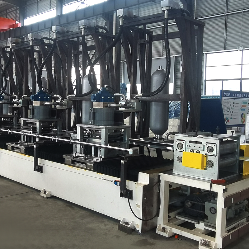
8-Axis servo punching solar PV bracket roll forming machine, flexible adjustment of punching position. Material decoiler with storage platform and robotic arm Feeder (to provide power f...
See Details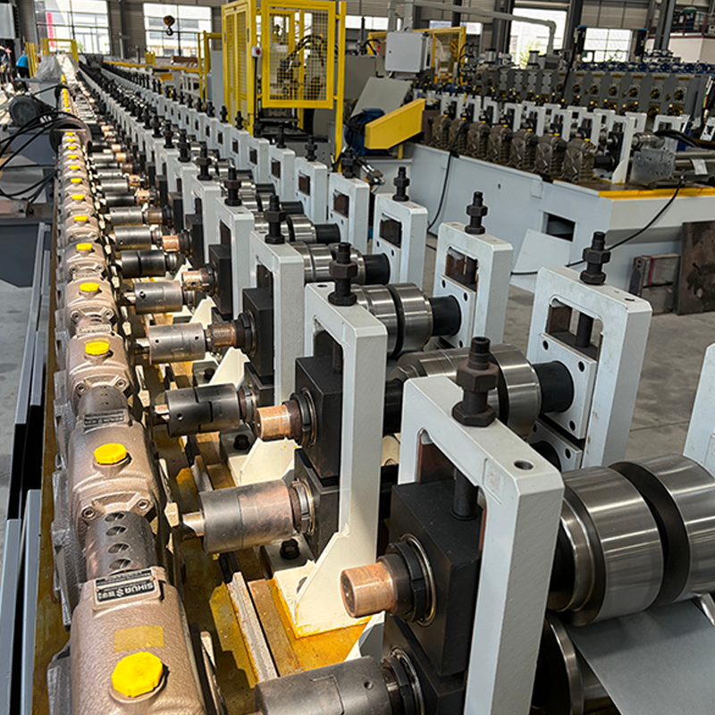
PV frame window door profile roll forming machine Worm gear reducers with different reduction ratios can be selected to achieve different production speeds. Straightening seats are used t...
See Details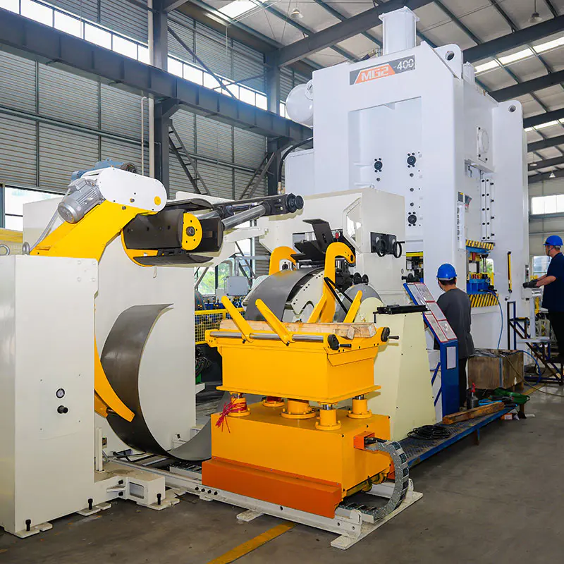
3-in-1 Decoiler Straightener Feeder System · 3-in-1 Decoiler Straightener Feeder capacity: 5 tons Hydraulic mandrel expansion Servo-driven straightening & feeding Synchronized signal wit...
See Details
wide material single decoiler Leveling machine and Machine for punching small holes on both sides All the upper and lower rollers are connected to a worm gear reducer.This makes the for...
See Details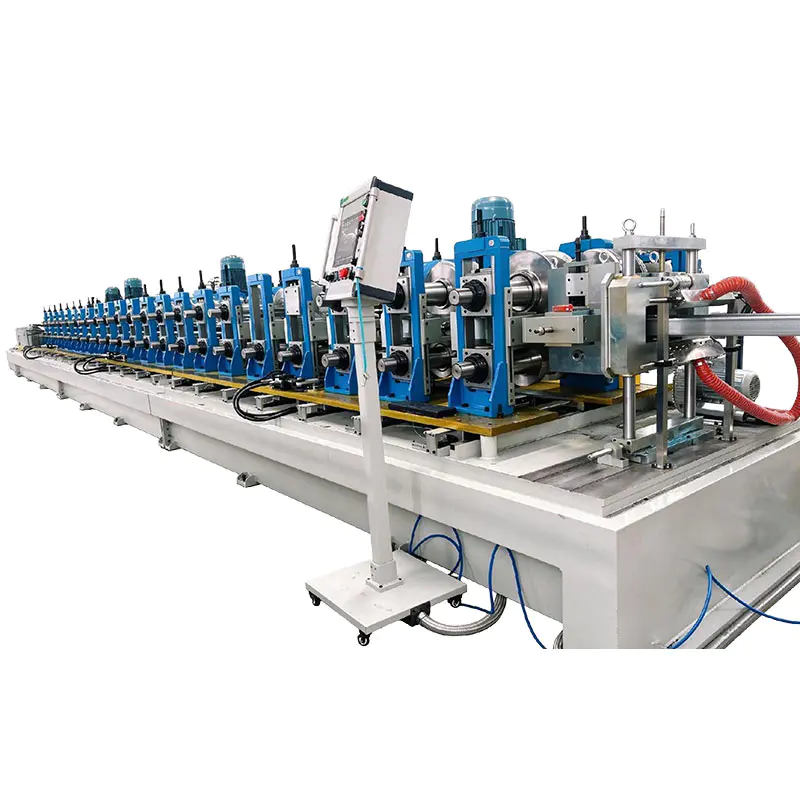
Decoiler System Double-Head Rotary Hydraulic Decoiler Capacity: 3 tons × 2 pieces Maximum material width ≤ 800 mm Hydraulic expansion coil Hydraulic expansion coil o Motor rotary exchange for...
See Details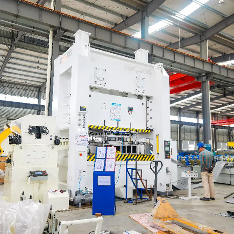
Decoiler System 3-in-1 Decoiler Straightener Feeder Capacity: 5 tons hydraulic coil mandrel expansion, servo feeding & straightening. Punching machine 400 Ton Power Press Capacity: ...
See DetailsDon't hesitate to contact when you need us!
Contact Information
PRODUCTS
Mobile


 English
 Español
 русский