Content
An upright rack roll forming machine is a specialized cold-roll forming production line engineered to continuously produce the vertical column profiles used in pallet racking, shelving systems, and storage rack structures. These column profiles — commonly called upright frames, rack columns, or rack posts — are the primary structural load-bearing elements of any selective pallet rack, drive-in rack, push-back rack, or cantilever rack system.
The machine takes flat steel coil strip as input and progressively shapes it through a sequence of paired roller dies into a finished open or closed cross-section profile, complete with punched teardrop, square, or round holes along the column face that serve as connector slots for beams, bracing, and other rack components. The entire process — from uncoiling to cut-to-length — runs in a single continuous line at speeds typically between 10 and 30 meters per minute, depending on material thickness, profile complexity, and punching frequency.
Upright rack roll forming machines are core capital equipment for rack manufacturers supplying warehousing, logistics, retail, and cold storage markets. The ability to produce certified structural profiles at high volume and consistent dimensional tolerance is a direct determinant of a manufacturer's competitive position in the global racking industry.
The cross-section geometry of the upright column profile defines the racking system's load capacity, connector compatibility, and material efficiency. Different market regions and rack manufacturers have established proprietary or standardized column profiles, and the roll forming machine must be tooled and calibrated specifically for the target profile geometry.
C-channel and open-section uprights are formed from a single strip bent into a C, U, or modified C-shape with return lips. They are structurally efficient in the roll forming process due to their relatively simple bending sequence and are widely used in medium-duty selective rack systems. The open-section geometry simplifies perforation tooling integration and allows beam connectors to engage from multiple directions.
Closed rectangular or square tube upright profiles provide superior torsional rigidity and higher axial load capacity than open sections of equivalent material weight. Roll forming a closed box section requires a seam-welding station integrated into the line — typically high-frequency induction welding (HF welding) — to close the profile after the forming passes. Box-section uprights are the standard choice for drive-in rack, very narrow aisle (VNA) rack, and heavy-duty pallet racking where column loads exceed the practical limits of open sections.
The hole pattern punched into the upright face is as commercially significant as the cross-section geometry — it determines compatibility with beam-end connectors from specific rack manufacturers and regional standards. Teardrop holes (a combination of a round hole and a narrower slot below it) are the dominant pattern in North American racking markets; square or rectangular slots are common in European systems; round holes on a defined pitch (typically 50 mm centers) are standard across many Asian markets. The roll forming line's punching press must be tooled and indexed precisely to the required hole pitch and pattern geometry.
| Profile Type | Typical Application | Welding Required | Dominant Market |
|---|---|---|---|
| Open C/U section | Light to medium selective rack | No | Global |
| Lipped C-section | Medium-duty selective rack | No | Americas, Asia-Pacific |
| Box/closed section | Drive-in, VNA, heavy-duty rack | Yes (HF welding) | Europe, Middle East |
| Roll-formed structural column | Mezzanine, cantilever rack | No / Optional | Global |
A complete upright rack roll forming production line integrates multiple sequential stations, each performing a specific operation. Understanding the function of each station is essential for evaluating equipment specifications, planning plant layout, and diagnosing production issues.
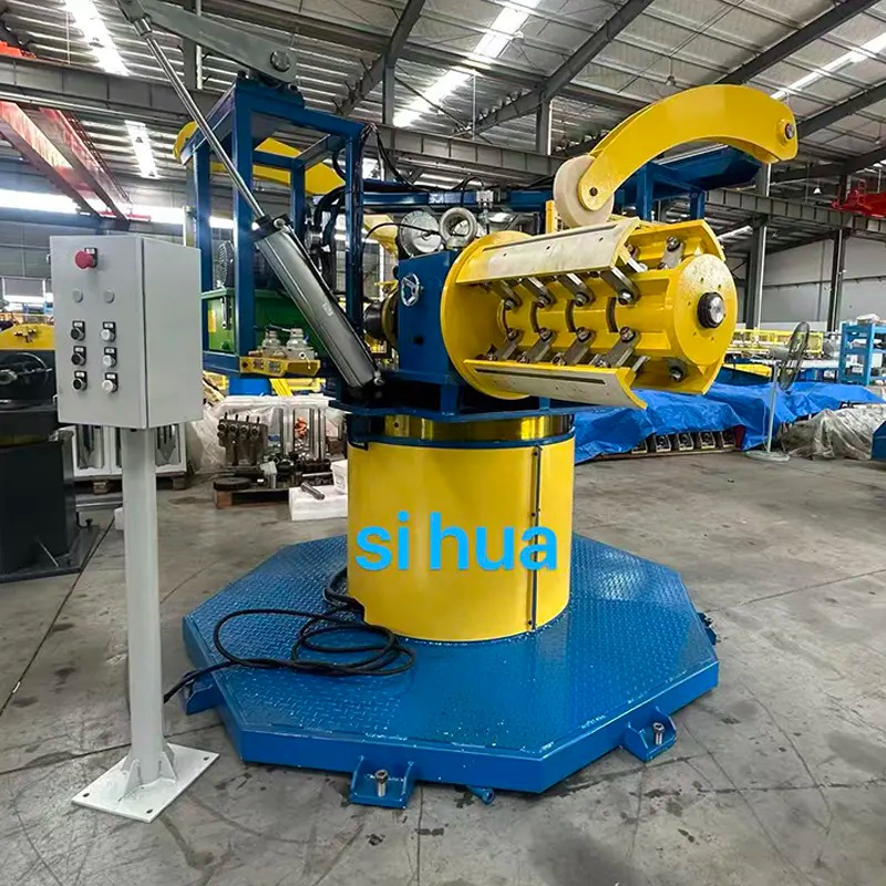
The line begins with a motorized or hydraulic decoiler that holds and unwinds the steel coil (typically 3–6 tonnes coil weight, 1.5–3.0 mm material thickness for structural rack uprights). A multi-roll straightener removes coil curvature and longitudinal bow from the strip before it enters the punching station. Strip edge guiding ensures the material enters the punch and forming stations with consistent lateral positioning — misalignment at this stage propagates as profile twist or hole-pitch error through the entire line.
In most upright rack roll forming lines, hole punching is performed on the flat strip before the forming passes — a pre-punching configuration. This approach allows the use of a fixed hydraulic or mechanical press with standard flat-die tooling, avoids distortion of already-formed profile walls, and maintains precise hole-to-hole pitch across the column length. The press is servo-controlled and synchronized with the line feed speed so that hole pitch remains accurate regardless of production speed variation. Hole pitch accuracy is critical: most rack beam connectors tolerate a positional tolerance of ±0.5 mm over a 50 mm pitch; deviations outside this range cause connector misalignment and beam-level errors in installed rack systems.
The forming mill is the heart of the line — a series of paired upper and lower forming roller stands (typically 12 to 24 stands for a structural rack upright profile) that progressively bend the strip from flat to final cross-section geometry. Each stand introduces a small incremental bend, distributing the total deformation across enough stages to avoid cracking, springback, or surface marking at the bend radii. Stand housings are typically fabricated from high-strength welded steel or cast iron; roller shafts are precision-ground and supported in anti-friction bearing housings that allow individual stand adjustment for alignment and gap setting.
The drive system transmits power to all forming stands simultaneously through a chain drive, gear coupling, or individual servo motor arrangement. Modern servo-driven mills eliminate mechanical coupling between stands, allowing each stand speed to be trimmed independently — improving strip tension control and reducing scrap at the start and end of each coil.
For box-section upright production, a high-frequency induction welding unit follows the final forming stands. Squeeze rolls press the open seam edges together while an HF coil (operating at 200–450 kHz) heats the steel at the weld point to forging temperature in milliseconds. The resulting solid-phase forge weld is then scarfed (excess weld bead removed) by a carbide scarfing tool immediately downstream. HF-welded rack upright tubes meet structural integrity requirements equivalent to cold-drawn tube — provided the welding parameters (power, frequency, speed, and squeeze pressure) are tightly controlled and verified by periodic destructive weld test.
A servo-controlled flying cut-off unit — either a cold-saw blade or a guillotine shear — cuts the continuous formed profile to programmed lengths without stopping the line. The cut-off carriage accelerates to match the profile exit speed, makes the cut, then returns to its start position for the next cut cycle. Length tolerance of ±1 mm or better is achievable with servo flying cut-off systems, which is necessary for upright frames that must be assembled to consistent height tolerances in installed rack structures. A programmable length controller allows operators to set multiple cut lengths in sequence, enabling a single production run to produce several upright lengths without changeover.
Cut uprights exit the line onto a run-out table with powered or gravity rollers that convey finished profiles to a bundling and stacking area. Automated stacking systems accumulate uprights into bundles of defined count, which are then strapped, labeled, and moved to coating (powder coat or galvanizing) or dispatch. Automatic stacking eliminates the bottleneck and injury risk of manual stacking at line exit and is standard practice in high-volume rack manufacturing operations.
When specifying or comparing upright rack roll forming machines, the following parameters most directly affect production capability, profile quality, and long-term operating cost.
Rack upright profiles produced on roll forming lines must meet dimensional and structural tolerances defined by national and international racking standards. The primary applicable standards are EN 15512 (European steel static storage systems design and testing standard), RMI ANSI MH16.1 (North American rack design standard), and AS 4084 (Australian standard for steel storage racking). These standards specify tolerances for upright cross-section dimensions, straightness, twist, hole position accuracy, and material yield strength that directly govern the safe load capacity of finished rack structures.
From a manufacturing process perspective, the critical quality control checks on roll-formed rack uprights include:
For rack manufacturers evaluating upright rack roll forming machine suppliers, the following questions move the conversation beyond catalog specifications toward a realistic assessment of the machine's fit for purpose:

wide material single decoiler Leveling machine and Machine for punching small holes on both sides All the upper and lower rollers are connected to a worm gear reducer.This makes the for...
See Details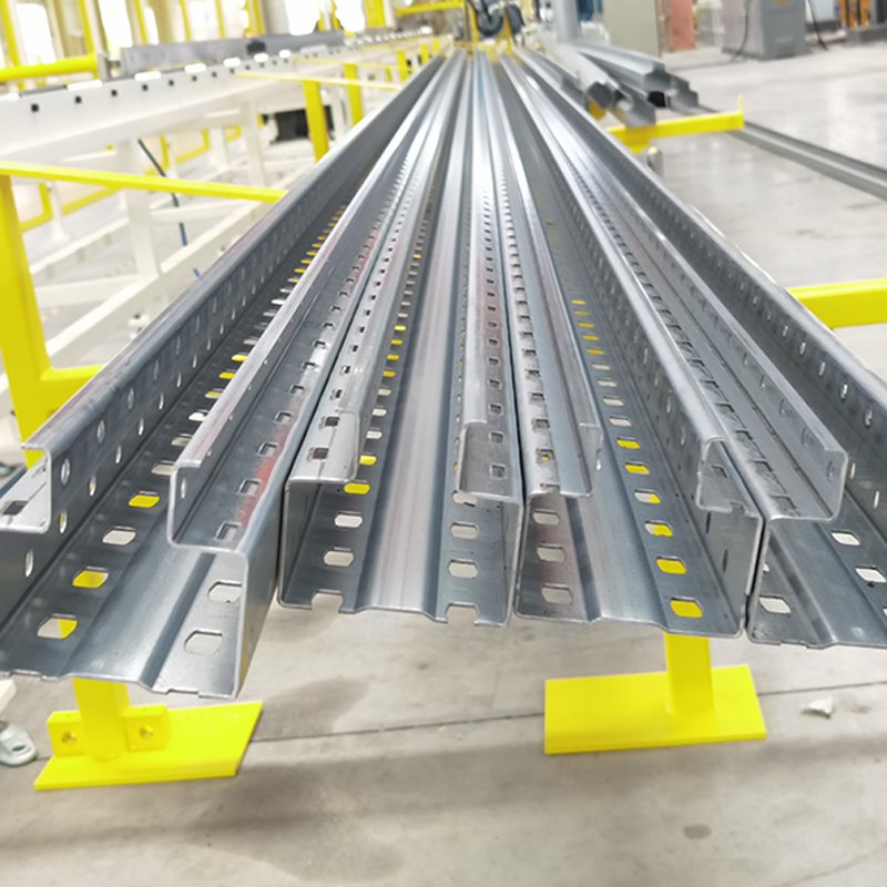
Upright rack roll forming machine, steel yield strength 250–550 MPa Single-head manual decoiler with feeding trolley Leveling before the press machine Yangli/Yadon press machine (o...
See Details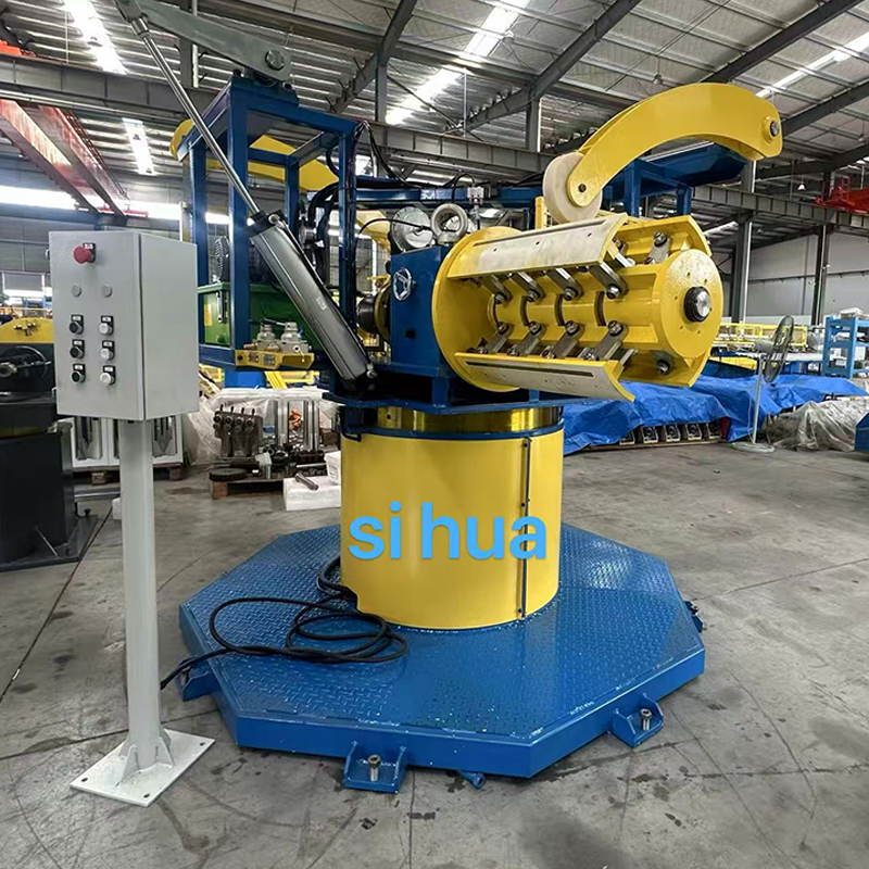
Double head rotating hydraulic heavy-duty decoiler.This equipment can automatically stop synchronously with the forming machine, and features hydraulic expansion and contraction as well as automa...
See Details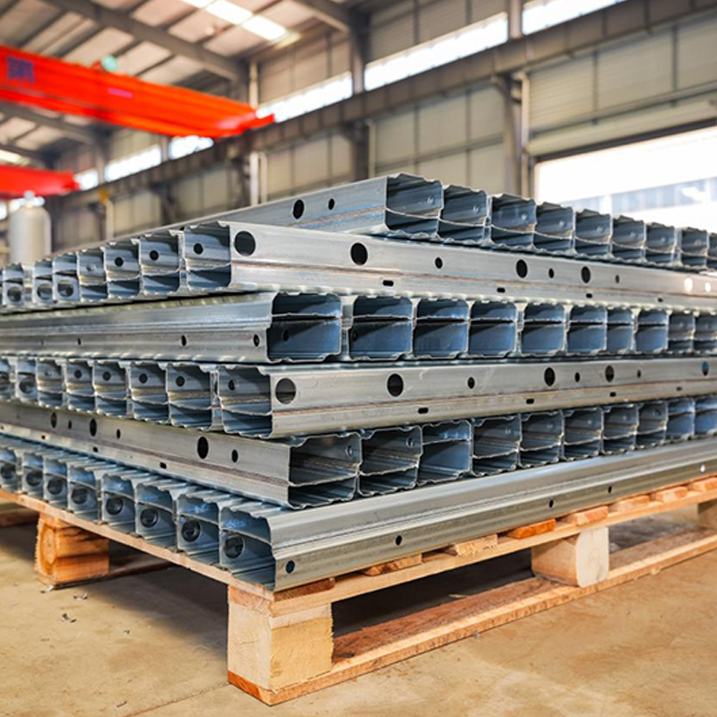
The production line for vehicle B-profile automotive chassis reinforcement beams involves several key processes to ensure High-strength, precision, and durability for vehicle applications. Key e...
See Details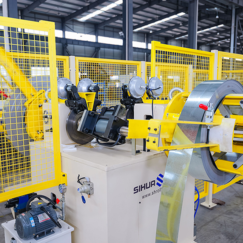
Automatic rotating double-head hydraulic decoiler with no-material detection, 5 tons per side. Laser power and welding length are adjustable to accommodate steel strips of various thicknesse...
See Details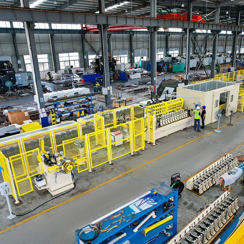
Automatic rotating double-head hydraulic decoiler with no-material detection, 5 tons per side. Quick-change cassette roll forming machine (changeover takes 30 minutes). Cutting without ...
See DetailsDon't hesitate to contact when you need us!
Contact Information
PRODUCTS
Mobile
 English
 Español
 русский